
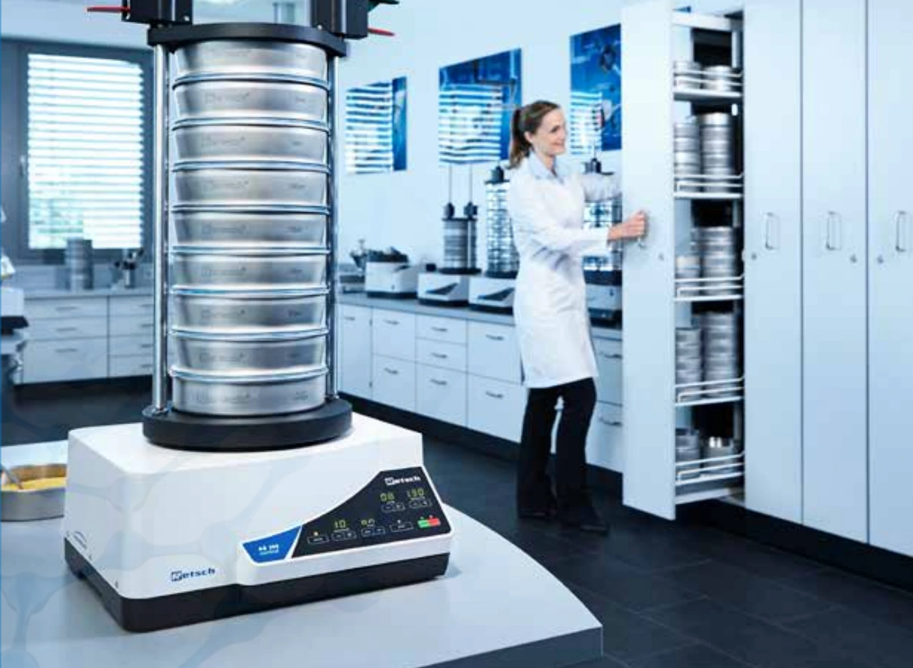
What is sieving?
Sieving separates particles by size using a mesh or perforated plate with known openings. Particles that fit through the openings pass to the next sieve or collecting pan. In sieve analysis, each retained fraction is weighed to determine the particle size distribution by mass.
A single sieve gives the mass above and below one size limit. A stack gives several size fractions that remain available for inspection or further testing. Particle shape and orientation affect whether a particle passes, so a sieve result describes size relative to an opening.
Which sieving method should you use?
| Method | When to consider it | How it separates |
|---|---|---|
| Dry vibratory | Free-flowing powders and granules | Vertical throw and circular motion spread and turn particles on a stack. |
| Wet | Fine particles that clump or cling and tolerate a liquid | A compatible liquid washes fines through the stack. |
| Horizontal | Elongated, flat or fibrous particles | Circular motion moves particles in the plane of the mesh. |
| Tap | Procedures that specify tapping | Vertical taps act alongside horizontal motion. |
| Air jet | Fine powders or a single sieve cut | A rotating jet disperses powder and suction draws fines through the mesh. |
- Size interval
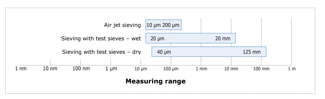
- Dry test sieving typically covers about 40 µm to 125 mm. Wet sieving can reach about 20 µm; air jet can reach about 10 µm.
- Material behavior
- Consider shape, bulk density, agglomeration, static charge and whether the sample can tolerate a liquid.
- Required output
- Use a stack for multiple fractions, or a single sieve cut to measure the share above and below one aperture.
- Test procedure
- Check the governing standard or lab method first. It may specify the motion, sieve series, load or endpoint.
Vibratory: vertical throw and circular motion
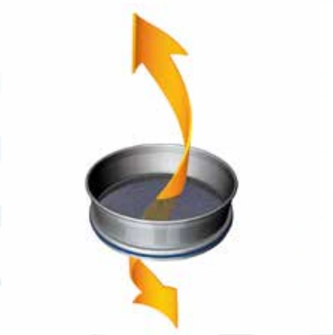
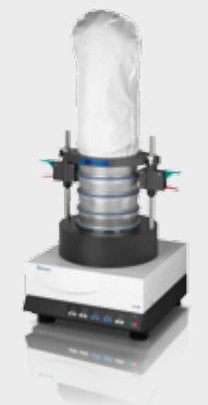
Vertical motion lifts and turns particles while circular motion distributes them over the mesh. The combination gives an irregular particle repeated opportunities to present a smaller cross-section to an aperture. The RETSCH AS 200 series, AS 300 Control and AS 450 models use this motion.
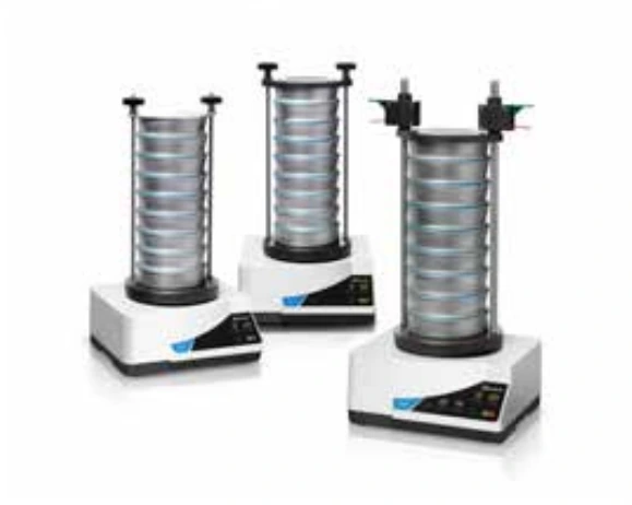
On the AS 200 Control, AS 300 Control and AS 450 Control, the natural frequency depends on the stack and sample load. The controlled acceleration setting adjusts amplitude as frequency changes. Use it when comparing runs that must maintain the same acceleration despite differences in load.
Wet: wash the fines through
Wet sieving can help when fine particles cling, form agglomerates or charge electrostatically. A compatible liquid, commonly water, carries fines through a suitable vibratory stack. Choose a liquid that does not dissolve, swell or otherwise alter the material being measured. If reporting fractions by dry mass, recover and dry them as required by the method before weighing.
Horizontal: circular motion in one plane
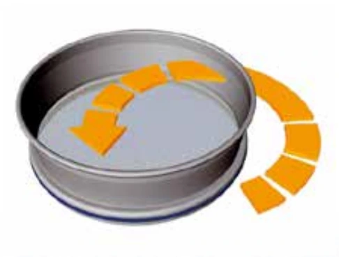
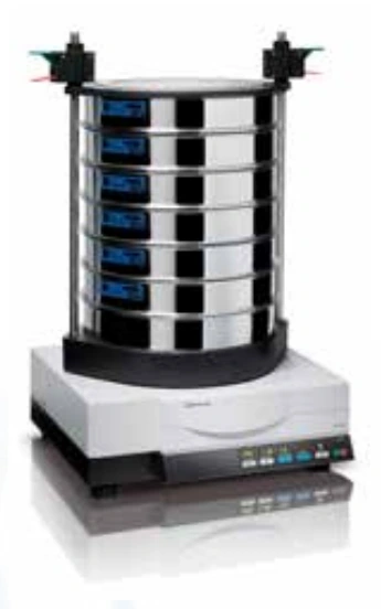
Horizontal motion suits some elongated, flat or fibrous samples because particles tend to keep their orientation. The RETSCH AS 400 Control operates at 50–300 rpm. The configuration described handles up to 15 kg and spans 45 µm to 63 mm, with 100 to 400 mm sieve formats depending on the setup.
Tap: horizontal motion plus vertical impacts
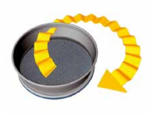
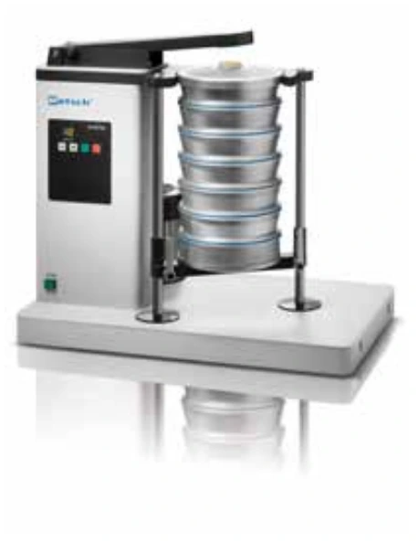
Use tap sieving where the test method prescribes it. The RETSCH AS 200 Tap combines 280 rpm circular motion with 150 taps per minute. It takes up to seven 200 or 203 mm sieves and a sample load up to 3 kg in the described configuration.
Air jet: one aperture per run
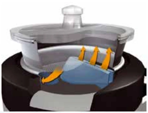
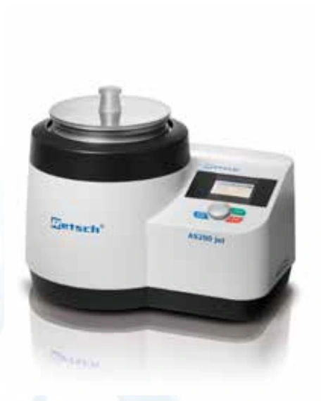
A vacuum draws air through a rotating slit nozzle under a stationary sieve. The jet lifts powder against the lid, helping disperse agglomerates, while suction draws undersize through the mesh. A cyclone can collect fines. The RETSCH AS 200 jet accepts 200 or 203 mm sieves; its specified instrument range is 10 µm to 4 mm. That range is distinct from the typical air jet interval in the chart. Open Mesh Function helps clear near-mesh particles, and automatic vacuum regulation is an option.
Compare six vibratory shaker configurations
These figures describe the configurations in the comparison. Maximum shaker load and permitted material on a single sieve are separate limits.
| Parameter | AS 200 basic | AS 200 digit cA | AS 200 control | AS 300 control | AS 450 basic | AS 450 control |
|---|---|---|---|---|---|---|
| Measuring range | 20 µm - 25 mm | 20 µm - 25 mm | 20 µm - 25 mm | 20 µm - 40 mm | 25 µm - 125 mm | 25 µm - 125 mm |
| Sieve diameter | 100 / 150 / 200 / 203 (8") mm | 100 / 150 / 200 / 203 (8") mm | 100 / 150 / 200 / 203 (8") mm | 100 / 150 / 200 / 203 (8") / 305 (12") / 315 mm | 400 / 450 mm | 400 / 450 mm |
| Amplitude (mm unless noted) | 1 – 100 % | 0.2 – 3.0 | 0.2 – 3.0 | 0.2 - 2.2 | 0.2 - 2 | 0 – 2.2 |
| Maximum load | 3 kg | 3 kg | 3 kg | 6 kg | 15 kg | 25 kg |
| Recalibration and sieve acceleration | - | - | yes | Yes | - | yes |
What is a sieve?
A sieve is a screen with openings of a known size. A laboratory test sieve typically holds woven wire mesh or a perforated plate in a rigid frame. The aperture is the opening through which a particle must fit. Frame diameter determines which shaker the sieve fits and how much screening area is available.
How do you choose a test sieve?
Start with the aperture required by your test procedure. Specify it in micrometres or millimetres because a mesh count alone does not state the opening size. Check the frame diameter, cloth or plate type, and load limits before assembling a stack.
Explore 200 and 203 mm woven wire test sieves or perforated plate sieves.
Take a representative test portion
1. Sample the bulk material
Decide where to collect increments and how much material is needed to represent the lot. Coarser and more heterogeneous material generally calls for a larger initial sample. As an example specific to coal, the DIN 51701 calculation illustrated here uses a factor of 0.07 kg/mm. A maximum particle size of 50 mm gives a minimum initial sample of 3.5 kg. Do not transfer this factor to unrelated materials.
2. Divide without losing size fractions
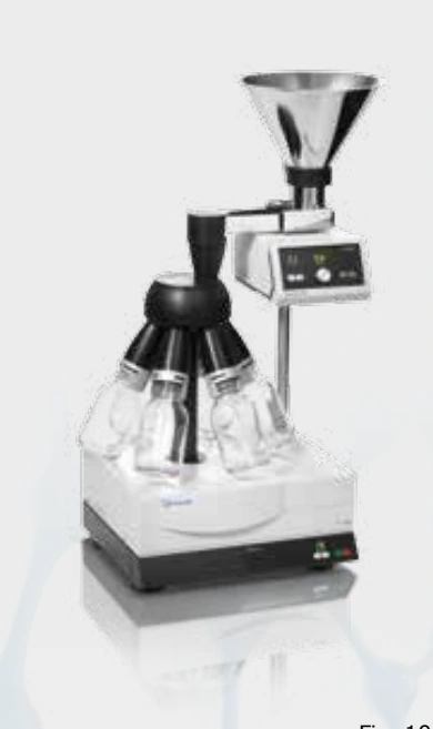
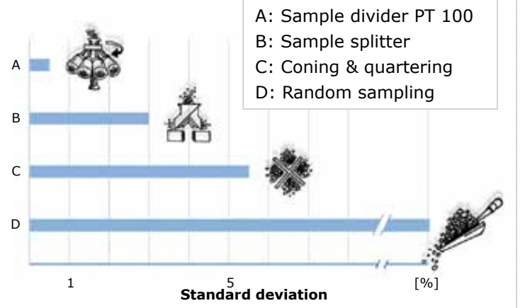
If the initial sample is too large, split it before loading the sieves. A rotary divider repeatedly cuts the falling stream into collection vessels. The RETSCH PT 100 uses a rotating head with 6, 8 or 10 outlets, depending on configuration. A splitter, coning and quartering, or a random grab can yield different variability; select and verify the division method for your material.
3. Select the sieves and check the load
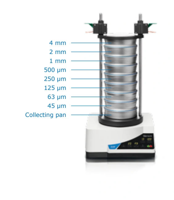
Choose apertures that cover the expected distribution, often at roughly logarithmic intervals such as a Renard R10/3 series. Match frame diameter and sieve count to the shaker. The coarsest sieve goes on top, the finest above the collecting pan. Check the permissible batch and the maximum retained volume at each aperture; overloading restricts access to the mesh.
At a 1 mm opening, the example allows 20 cm³ retained per square decimetre: about 63 cm³ for a 200 mm sieve or 252 cm³ for a 400 mm sieve. The 200 mm example allows a 126 cm³ initial batch. Convert volumes to mass using the sample's bulk density. The illustrated upper particle-size estimate, xmax = 10 × w0.7 with w entered in millimetres, gives 3.79 mm for a 250 µm aperture. Use the limits specified by your test procedure.
| Mesh size | Max. batch | Max. permitted sieve oversize |
|---|---|---|
| 25 µm | 14 cm3 | 7 cm3 |
| 45 µm | 20 cm3 | 10 cm3 |
| 63 µm | 26 cm3 | 13 cm3 |
| 125 µm | 38 cm3 | 19 cm3 |
| 250 µm | 58 cm3 | 29 cm3 |
| 500 µm | 88 cm3 | 44 cm3 |
| 1 mm | 126 cm3 | 63 cm3 |
| 2 mm | 220 cm3 | 110 cm3 |
| 4 mm | 346 cm3 | 173 cm3 |
| 8 mm | 566 cm3 | 283 cm3 |
Set the motion, run and recover
4. Set amplitude and time
Use prescribed settings where available. Otherwise, compare trials at a fixed load. Too little throw gives particles little chance to turn; too much can make them miss mesh contacts. The aim is frequent particle-to-aperture encounters. A 1.2 mm full stroke means ±0.6 mm about the resting position.
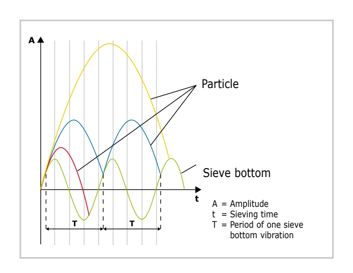
For the DIN 66165 endpoint example, continue until an additional minute passes less than 0.1% of the feed mass through the sieve being checked. Record load, aperture sequence, motion setting, time, any approved sieving aid and the endpoint criterion.
5. Run a stacked analysis
- Inspect and weigh each clean sieve and the empty pan.
- Assemble the stack in descending aperture order. Use only sieving aids allowed by the method.
- Weigh the test portion, place it on the coarsest sieve and clamp the stack.
- Run at the selected amplitude or speed and time. Check the specified endpoint.
- Weigh each sieve and pan with its retained fraction. Subtract the empty weights and check mass recovery.
6. Recover each fraction
Transfer fractions separately if you need to examine, retest or process them. Take care to recover material from the pan and mesh without mixing adjacent fractions or forcing particles through the wire.
Read a 150 g worked example
7. Calculate the retained fractions and cumulative passing
Subtract the empty sieve mass from its loaded mass. Divide each retained mass by the analysis mass and multiply by 100 to get the mass percentage. For cumulative percent passing a given aperture, add the fractions collected below that sieve, including the pan. Use the denominator specified by your procedure if there is unrecovered material.
Percent passing = (mass collected below the selected sieve ÷ analysis mass) × 100.
Here, the 250 µm sieve retains 48 g between 250 and 500 µm, or 32% of the 150 g recovered. The fractions below that sieve total 55.5 g: 37% passes 250 µm in the table. The last column sums retained fractions from the pan through the listed row; to read passing at a given aperture, use the preceding row. The annotated curve shows about 36% at 250 µm and a median near 330 µm. Use the measured table for exact sieve cut results and the curve to estimate values between apertures.
| Sieve aperture (µm) | Empty (g) | Loaded (g) | Retained (g) | Retained (%) | Cumulative retained from pan (%) |
|---|---|---|---|---|---|
| Pan | 501 | 505.5 | 4.5 | 3 | 3 |
| 45 | 253 | 259 | 6 | 4 | 7 |
| 63 | 268 | 283 | 15 | 10 | 17 |
| 125 | 298 | 328 | 30 | 20 | 37 |
| 250 | 325 | 373 | 48 | 32 | 69 |
| 500 | 362 | 384.5 | 22.5 | 15 | 84 |
| 1,000 | 386 | 401 | 15 | 10 | 94 |
| 2,000 | 406 | 412 | 6 | 4 | 98 |
| 4,000 | 425 | 428 | 3 | 2 | 100 |
| Total | = 150 g | = 100 % |
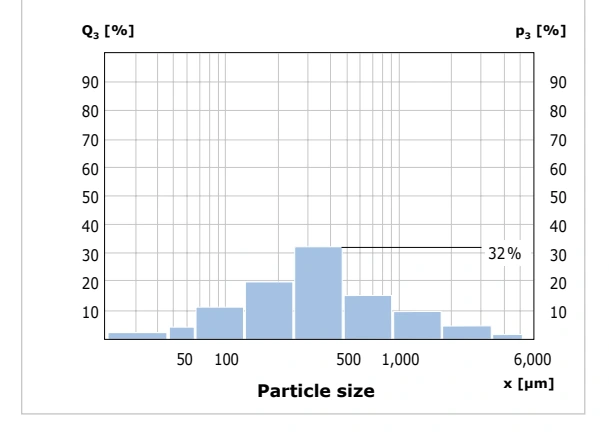
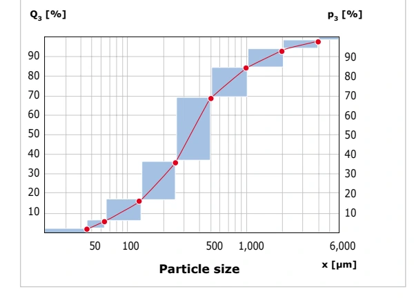
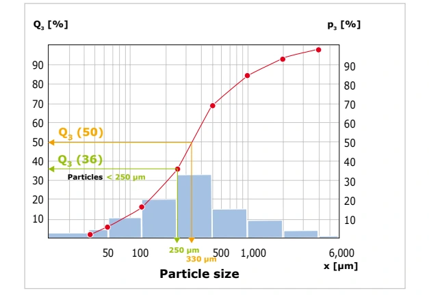
Check mass balance. Subtract the sum of all retained fractions from the starting mass and report that difference relative to the feed. In the DIN 66165 example, a loss above 1% calls for repeating the analysis. The table accounts for the full 150 g. Results can be calculated manually or with evaluation software such as RETSCH EasySieve®.
Clean, dry and inspect the sieves
8. Protect the mesh between runs
Invert the sieve and tap it lightly to dislodge trapped particles. Never push the sample through the wire. Follow the sieve instructions for brushing: a soft brush on the underside may help free a lodged particle, a plastic bristle brush can be suitable above 500 µm, and an approved ultrasonic bath is generally preferred for finer cloth.
Remove rubber or plastic seals before cleaning or drying where the assembly permits. For the cabinet procedure described here, place sieves upright and stay at or below 80 °C to protect fine wire tension. A RETSCH TG 200 Fluid Bed Dryer can dry compatible 200 or 203 mm sieves. Inspect mesh uniformity and replace damaged sieves before using them for quality control.
Plan a sieve analysis with Glen Mills
Bring your material, estimated size range, available test mass, required cut points and any prescribed procedure. Include known issues such as static, clumping or liquid sensitivity. These details help narrow the choice of shaker, sieves and test settings.
Compare sieve shakers · Discuss material testing · Request information or a quote