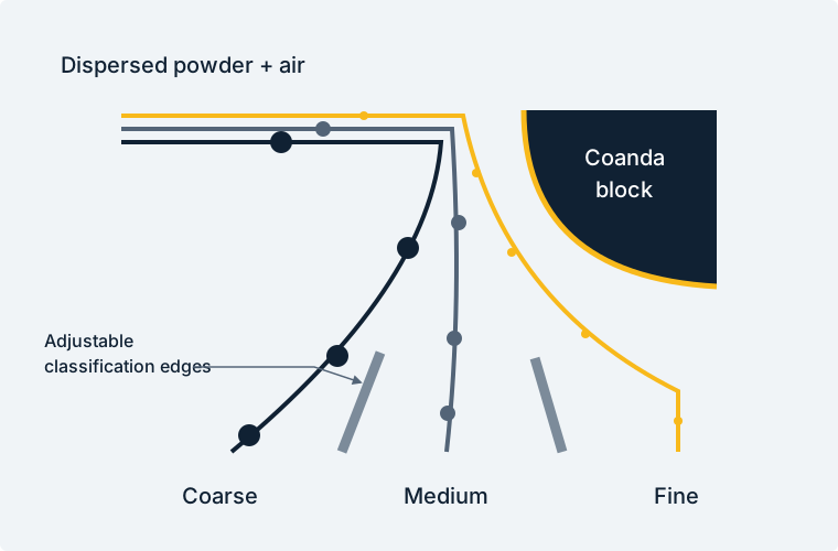
Coarse fraction
Collect particles with greater inertia, farther from the curved airflow.

COANDA AIR CLASSIFICATION EQUIPMENT
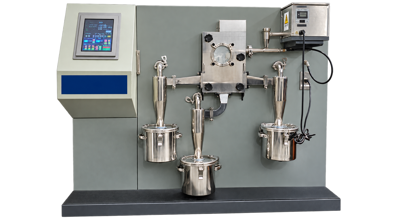
Separate fine, dry powders into controlled fractions using airflow and adjustable classification edges, with no rotating classifier wheel.
THE COANDA EFFECT
An air jet tends to follow a nearby curved surface. Fine particles follow that path more closely; particles with greater inertia travel farther away. Adjustable edges divide the resulting streams.
An ejector uses compressed air to disperse the feed and deliver particles through the material nozzle.
The curved Coanda block and differences in particle inertia create distinct paths through the classification zone.
Adjust the classification edges to collect the desired cut and separate finer and coarser material.
PARTICLE SIZE & FRACTION CONTROL
Evaluate fine and coarse cut points together. The system can collect three fractions simultaneously, so the target product can be recovered between the two cuts.
Collect particles with greater inertia, farther from the curved airflow.
Recover the product between your selected fine and coarse cut points.
Collect particles that follow the airflow more closely along the Coanda block.
Particle range is application dependent. It is not a guaranteed cut point, yield or classification efficiency for every material. Confirm results with a representative trial.
LABORATORY TO PRODUCTION
Compare feed capacity, total airflow and power together. The required fraction, feed condition and material properties guide the configuration and achievable processing rate.
| Configuration* | Feed capacity kg/h | Total airflow m³/min | Rated power kW | L × W × H inches |
|---|---|---|---|---|
| Laboratory | 1-5 | 2 | 2.5 | 65 × 41 × 55 |
| Small batch | 3-15 | 2.7 | 4.5 | 77 × 61 × 62 |
| 05 | 10-70 | 4-6 | 8-12 | 114 × 114 × 118 |
| 15 | 30-200 | 9-15 | 16-23 | 185 × 157 × 138 |
| 30 | 60-400 | 14-24 | 20-38 | 201 × 169 × 169 |
| 45 | 90-600 | 20-33 | 23-46 | 217 × 177 × 177 |
| 60 | 120-800 | 25-42 | 31-56 | 240 × 205 × 201 |
| 75 | 150-1,000 | 31-51 | 39-77 | 256 × 228 × 217 |
| 90 | 180-1,200 | 36-61 | 45-86 | 268 × 236 × 232 |
| 105 | 210-1,400 | 41-69 | 47-92 | 272 × 240 × 236 |
| 150 | 300-2,000 | 58-96 | 77-112 | 295 × 260 × 256 |
*Configuration labels describe laboratory, small-batch and size-series arrangements. Capacities depend on the powder and separation task. Dimensions refer to a standard equipment layout; discuss available space, collection, compressed air and installation requirements with Glen Mills.
MATERIALS & PROCESS GOALS
Air classification is a useful route to evaluate when abrasive material, fine cut points or product purity make the classification method especially important.
A classification chamber without a rotating wheel reduces one source of wear. Review all product-contact surfaces and acceptable contamination.
Evaluate graphite and other fine powders against the required size distribution and yield.
Discuss additive manufacturing feedstocks, fraction recovery and the handling requirements of the material.
Review titanium dioxide, silica, advanced ceramics, APIs and specialty powders for suitable dry classification.
PLAN THE APPLICATION
The classification stage separates the feed into fractions. If the starting particles need size reduction, discuss milling upstream of classification.
This design uses the Coanda effect and adjustable classification edges instead of a rotating classifying wheel. The airflow and particle trajectories create the separation.
The classifier is designed to separate fine, dry powders. Moisture, agglomeration and poor dispersibility can change the result; share those properties during the application review.
Bring a representative feed and define the desired particle-size distribution, product yield and throughput. A trial can compare settings and measure each collected fraction.
TALK WITH GLEN MILLS
Start with the material and the result you need. Our team can help review equipment, test requirements and quotation.